%20Small.jpg)
Adding A Digital Clock And IF Xtals To The WWV Receiver
%20Small.jpg)
|
Update Jan 2018 Finally after 15 years of searching I was able to get hold of the pair of IF crystals that were missing when I first got this receiver in 2003. They came out of a Lavoie LA-800D that is just about identical to the General Microwave model I have. I managed to connect with Dave W5WP who had a Lavoie with good crystals in it and it ended up on my bench. Thanks Dave. I decided to fill the ugly holes made by a previous owner of this General Microwave Model 550 WWV Receiver. The previous owner was going to add a digital clock timed to WWV but only got as far as making the holes. And he made some huge holes at that. I decided that I would complete his attempt just to get the holes filled. Started this project in early 2017 and finished it in Oct 2017. Actually it came out pretty good and actually seems fitting for the unit since frequency and time are inversely related to each other. My high level plan was to use the 1Mhz derived from my URQ-10A frequency standard that was aligned to NIST with the WWV receiver. I also wanted to be able to switch to the internally generated 10MHz derived from the WWV signal in the receiver. I did not want to use only the internal 10MHz because that would mean the WWV receiver would have to be on all the time. I wanted the clock to display time even though the unit was turned off. Therefore I was primarily going to use the external 1MHz from the frequency standard for the clock timing. I spent quite a bit of time designing and breadboarding to come up with a final reliable circuit design. I first had to learn something about digital clocks though. So I bought a cheap DIY Clock on ebay for $10 bucks. |
|
|
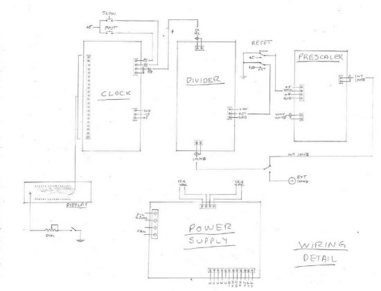 Clock Block Diagram |
Clock timing is either internal WWV 10MHz or external 1MHz. If internal is selected the WWV 10MHz first needs to be divided down to 1MHz in the Prescaler Board and is applied to the int/ext timing select switch on the rear panel. If external 1MHz is selected timing source is from a rear panel BNC that has 1MHz applied to it. Which ever 1MHz is selected it is input to the Divider Board which divides the 1MHz down to 50Hz which gets applied to the Clock Board. The Clock Board then drives the LED Display Board. The Power Supply is always hot as long as the WWV Receiver is plugged in. I did this so the clock would always be on even if the receiver itself was switched off. It does require manually syncing the clock to WWV using the Fast Slow set buttons and the reset switch which zero's out the counters until the WWV "at the tone time will be" is heard at which time gets switched to normal to start counting in time with WWV. I added an LED display dimmer primarily to fill one of the mondo holes in the front panel. I also added a display on/off switch to fill another one of the huge holes. The switch only breaks the LED display path to ground so the count is not affected and time stays sync'd even if the display is turned off. Power Supply produces a +10 volts, +5volts, and -10volts. |
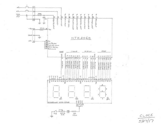 Clock & LED Display Scat |
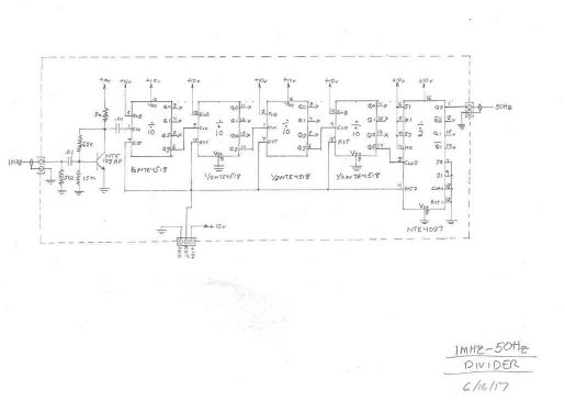 1MHz - 50Hz Divider Scat |
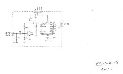 10MHz Prescaler Scat |
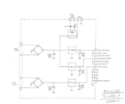 Power Supply Scat |
|
Clock and LED Display For the LED display I used a Kingbright CC56-11EWA. This display does not have a colon but only a single dot at the bottom. I tied this to the 1Hz output from the clock chip so it flashes every second. I set it up for 12 hour display rather than 24 hour to keep the parts count and display wiring to a minimum. The LED display does use a common cathode and this is where I put the display on/off switch and the dimmer pot. 1MHz - 50Hz Divider For the divider I had to divide the 1MHz external clock reference by 10 four times to get down to 100Hz and then divide by 2 to get to 50Hz for the clock timing. I bread boarded several dividers using both TTL and CMOS dividers. I settled on the CMOS NTE4518 dual BCD counter which gave me 2 divide by 10 stages in a single chip so I only needed two of these devices to get down to 100Hz. I used +10v as a supply voltage so the clock in signal had to be at least half supply voltage or +5v to trigger a count. My 1MHz input had to be amplified to get it up in level to trigger a count. I designed the amplifier using the general purpose NTE123AP transistor which worked very well. To get the final 50Hz I had to divide by 2. I used half of a NTE4027 dual flip-flop to get the final divide by 2 required. The reset lines were tied together and under normal count conditions has a ground on it. Switching a +10v on the reset line zero's all the counters and no count will occur until it's grounded again. 10MHz Prescaler For internal clock timing I used the 10MHz created in the WWV receiver from the received WWV signal. This had to be divided down by 10 to get to the 1MHz needed to apply to the 1MHz - 50Hz divider. For this division I used a TTL 7490A Decade counter simply because it was what I had on hand. The internal 10MHz from the receiver is a 200mv P-P signal so it had to be amplifed first to get it up to at lease half the TTL supply of +5v or 2.5v to be able to trigger the TTL counter. I again used a general purpose NTE123 for this purpose. I did discover though that the NTE123A in a metal can package had much better response at 10MHz than the NTE123AP plastic package. The circuit is identical to the Divider amplifier except for the transistor used. The circuit worked well. The reset line again is normally at ground for normal counting, applying +5v zero's the counter and stops any counting. Power Supply The power supply is pretty standard using 3-terminal regulators to produce +10v, +5v, and -10v. The power supply is wired so it's live all the time so the clock will display time even if the receiver is turned off. As part of this project I also added a fan to help cool the receiver as I felt it was getting way to warm when in the cabinet. I only wanted the fan on when the unit was turned on. To accomplish this I used an optical switch. I tapped off the 6.3vac filament line of the receiver to activate the LED in the optical switch and close the switch applying DC voltage to the fan. |
|||
|
|
|||
|
|
|
|
| Here's some top side views with boards installed. Top side of the chassis got the Clock Brd, Display Brd, 1MHz - 50Hz Divider Brd, and the -V Transformer. | ||
|
|
|
| Here's some under side views with boards installed. Under side of the chassis got the 10MHz Prescaler Brd, Power Supply Brd, and the +V Transformer. | |
|
|
|
| Putting in The IF Crystal Pair | |
| I originally picked up this General Microwave 550 WWV Receiver back in 2003. My original rebuild can be viewed here. The problem was it did not have the IF crystal pair which provides a BW of 50Hz. I was able to dig up a single 475KHz crystal and while it worked it was no were near the spec'd 50Hz BW. This lack of BW caused noise and modulation side bands to affect the display. I could not get a clean half moon lissajous on the display as well as getting good clean beat audio absent of modulation. For 15 years I lived with this problem as the crystal pair seemed pretty much un-obtainum. Then 2017 I made a connection with Dave W5WP who had a Lavoie version of the receiver. We made the deal and I soon had it on my bench with a good set of IF crystals in Jan 2018. I installed the crystals, found the center freq of the pair and aligned the receiver to this center frequency. It works beautifully as intended now. I get a very clean half moon and tuning the LO Trim has a very sharp and distinct point when on center frequency. The beat audio is pure beat now, no modulated audio at all, I can actually hear the beat signal very distinctly now. The original speaker was also in bad shape with a hole in the cone and several tears in the cone I repaired with nail polish. So as a plus I was also able to replace the speaker with the Lavoie speaker. Additionally I took the speaker bezel from the Lavoie as it help improve the front panel symmetry on my receiver. Looks really good now and works really good now. | |||
 |
%20Small.jpg) |
%20Small.jpg) |
%20Small.jpg) |
| Here's a pic of the Lavoie the crystal pair came from. It's virtually identical to the General Microwave version. | Here's a shot with the new crystals installed. Located on the left rear | Here's a front view of it finished. Nice half moon display and the added speaker bezel really helped even out the front panel symmetry. The added clock looks awesome. This piece is finally fully done. | Here it is taking it's place in my shop Frequency Standard Rack |